कंप्रेसर डिज़ाइन पर 7 युक्तियाँ (छात्रों और अभ्यास करने वाले इंजीनियरों के लिए)
This is a topic on which there's plenty of material in engineering text books and on the internet. However often, teachers, professors and sometimes even practicing engineers tend to explain these calculations as if they are teaching themselves only to leave students with stars revolving around their heads!!
With the advent of engineering software, calculating by hand is becoming a dying art and practicing engineers as they move up their careers, often end up saying "Computer Says....." like David Walliams in Little Britain!! without realizing what kind of data, a software uses to arrive at the results!! Therefore the Author has made an attempt to put himself into the shoes of the other and makes an attempt to explain.
 Click Here to Join the Over 3200 Students Taking our Highly Rated Courses on Quality Assurance/Quality Control, Project Management, Engineering, Food Safety, Lean Six Sigma, Industrial Safety (HSE), Lean Manufacturing, Six Sigma, ISO 9001, ISO 14001, ISO 22000, ISO 45001, FSSC 22000, Product Development etc. on UDEMY.
A Case Study
It has been proposed to install a centrifugal compressor with an electric motor for hydrocarbon gas pipeline transmission. In order to meet the requirements, a centrifugal compression system needs to be designed. The compressor's characteristic curves and gas process conditions at the compressor flange are taken as follows for demonstration.
Input Data

The driver is an electric motor. For the exercise, the type of motor chosen is an Asynchronous Induction Type Motor - 4 Pole, 50 Hz configuration with 1% slip. Also note that the compressibility factor is 0.9964 at both the suction and discharge since the pressure's are very low i.e., of the order of 1 bar(a) to 4 bar(a) range.
 Click Here to Join the Over 3200 Students Taking our Highly Rated Courses on Quality Assurance/Quality Control, Project Management, Engineering, Food Safety, Lean Six Sigma, Industrial Safety (HSE), Lean Manufacturing, Six Sigma, ISO 9001, ISO 14001, ISO 22000, ISO 45001, FSSC 22000, Product Development etc. on UDEMY.

What do We Need to Find out??
Before venturing into some number crushing, it helps to understand some basic terms.
Isothermal Compression - This is like a detractor who tries to knock you down and magically expects you not to get angry!! The term 'Iso' is associated when, If a parameter (e.g., temperature, pressure) does not change even when an external force acts on a system. When a Gas is compressed, its temperature increases and does not remain constant. Isothermal compression might work in Wonderland but on planet earth, gas compression is not isothermal and always produces heat and rise in temperature (even if he is Superman).
Isentropic/Adiabatic Compression - This is like the guy suffering from convulsions and and turns green. The term 'adiabatic' is used when the compressed gas does not exchange heat with the surroundings. If the compressed gas can magically prevent the produced heat from escaping to its surroundings through the metal of the compressor casing, then we would have an adiabatic/isenropic compression taking place.
Polytropic Compression - This is what happens in a real situation. When gas is compressed, some of the heat stays within the gas, while some of it accumulates in the metal casing (that's why surfaces get hot) and some of it escapes to the surroundings. Therefore making calculations using polytropic compression methods is a more realistic approach.
 Click Here to Join the Over 3200 Students Taking our Highly Rated Courses on Quality Assurance/Quality Control, Project Management, Engineering, Food Safety, Lean Six Sigma, Industrial Safety (HSE), Lean Manufacturing, Six Sigma, ISO 9001, ISO 14001, ISO 22000, ISO 45001, FSSC 22000, Product Development etc. on UDEMY.
Calculations
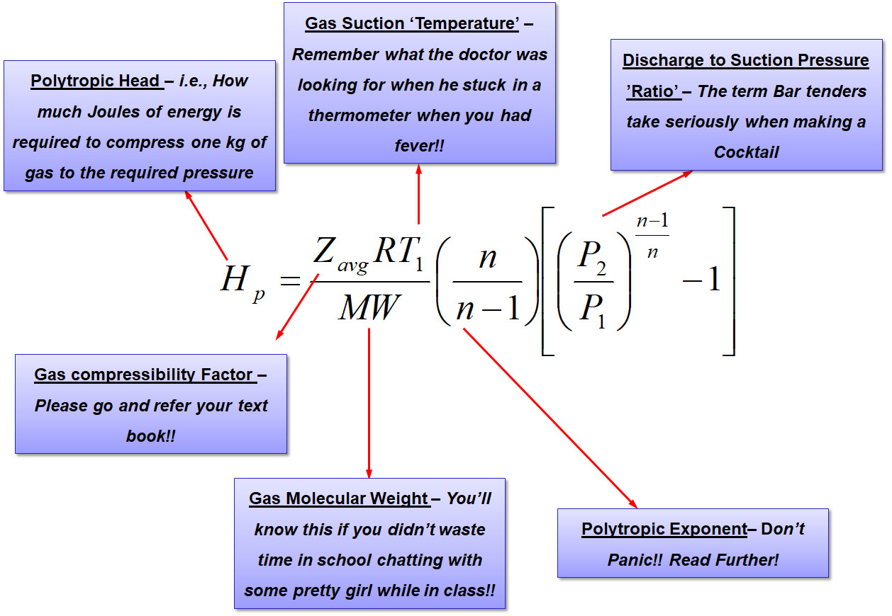
Proceeding on the lines of taking that the gas is compressed polytropically, it all begins with the basic equation as shown below,

The purpose of the above equation is to estimate how much energy is required to compress the 1.23 bar(a) at 25 deg.C hydrocarbon gas to 3.7 bar(a). Additionally since the gas temperature is expected to rise, it would be necessary to know by how much the discharge temperature increases.
 Click Here to Join the Over 3200 Students Taking our Highly Rated Courses on Quality Assurance/Quality Control, Project Management, Engineering, Food Safety, Lean Six Sigma, Industrial Safety (HSE), Lean Manufacturing, Six Sigma, ISO 9001, ISO 14001, ISO 22000, ISO 45001, FSSC 22000, Product Development etc. on UDEMY.
Polytropic Exponent Estimation
In the above equation, certain values like 'n' i.e., polytropic exponent is not available, but the good news is that, it can be calculated with another equation as follows,

In the above equation, 'k' is the ratio of specific heats, i.e., Cp/Cv and 'Np' is the polytropic efficiency. Therefore beginning the calculations with 'Np' taken from the compressor polytropic efficiency curves (comes to ~72%) and using the gas properties from the input data, the value of polytropic exponent 'n' is computed as follows,

 Click Here to Join the Over 3200 Students Taking our Highly Rated Courses on Quality Assurance/Quality Control, Project Management, Engineering, Food Safety, Lean Six Sigma, Industrial Safety (HSE), Lean Manufacturing, Six Sigma, ISO 9001, ISO 14001, ISO 22000, ISO 45001, FSSC 22000, Product Development etc. on UDEMY.
Gas Discharge Density Estimation
The compressed gas exits at the compressor discharge flange. The density of this gas can be estimated as,


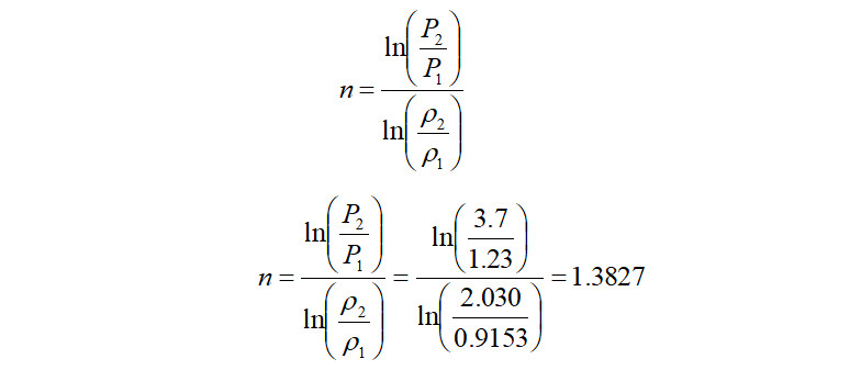
Alternately, in the case where the discharge density is known, the above equation can be directly used to calculate the polytropic exponent as follows,

 Click Here to Join the Over 3200 Students Taking our Highly Rated Courses on Quality Assurance/Quality Control, Project Management, Engineering, Food Safety, Lean Six Sigma, Industrial Safety (HSE), Lean Manufacturing, Six Sigma, ISO 9001, ISO 14001, ISO 22000, ISO 45001, FSSC 22000, Product Development etc. on UDEMY.
Polytropic Head Calculation
It is seen that the value of ‘n’ calculated using the above logarithmic equation is almost equal to the value calculated using the graph. Using the above logarithmic based 'n', the polytropic head produced is therefore,

Compressor Absorbed Power Calculation
From the above 'Hp' calculated, it indicates that to compress 1 kg of gas from 1.23 bar(a) to 3.7 bar(a), 173.7 kJ of energy is required. Therefore when computing the quantity of energy that is required to compress 7,413 kg/h of the same gas at a polytropic efficiency of ~72%, it comes to,

 Click Here to Join the Over 3200 Students Taking our Highly Rated Courses on Quality Assurance/Quality Control, Project Management, Engineering, Food Safety, Lean Six Sigma, Industrial Safety (HSE), Lean Manufacturing, Six Sigma, ISO 9001, ISO 14001, ISO 22000, ISO 45001, FSSC 22000, Product Development etc. on UDEMY.
Gas Discharge Temperature Calculation
The Gas Discharge Temperature can be calculated using the equation,

Adiabatic Efficiency Calculation
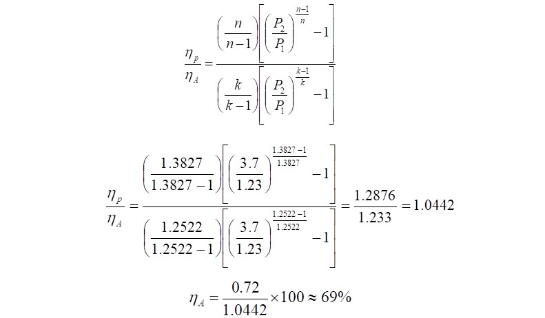
As an additional step, the adiabatic efficiency can be calculated as,

 Click Here to Join the Over 3200 Students Taking our Highly Rated Courses on Quality Assurance/Quality Control, Project Management, Engineering, Food Safety, Lean Six Sigma, Industrial Safety (HSE), Lean Manufacturing, Six Sigma, ISO 9001, ISO 14001, ISO 22000, ISO 45001, FSSC 22000, Product Development etc. on UDEMY.
Total Power Required
It is to be noted that the power calculated so far, is the power absorbed by the compressor to raise pressure from 1.23 bar(a) to 3.7 bar(a). Theoretically if the electric motor used to drive the compressor is 100% efficient, then this is the power delivered by the motor to the compressor. However in reality no system is perfect and hence requires to be compensated for the deficiency. Assuming mechanical losses between the compressor and electric motor and a gear box, if present, for the sake of this exercise a value of 20% is assumed. In reality, these numbers are to be consulted for with the turbo machinery vendor. With a 20% margin, the power required to be delivered by the motor comes to,

Hence in this exercise, the total power that the electric motor must deliver during running conditions to arrive at the 3.7 bar(a) pressure at the compressor discharge is ~600kW. The discharge temperature would be ~131 deg.C.
 Click Here to Join the Over 3200 Students Taking our Highly Rated Courses on Quality Assurance/Quality Control, Project Management, Engineering, Food Safety, Lean Six Sigma, Industrial Safety (HSE), Lean Manufacturing, Six Sigma, ISO 9001, ISO 14001, ISO 22000, ISO 45001, FSSC 22000, Product Development etc. on UDEMY.
Compressor Standard Flow Estimation
Although in the exercise, the flow was indicated as mass flow of 7,413 kg/h, compressor flow is measured using the units 'MMSCFD' which stands for Million Standard cubic feet per day in the industry. The need to use standard conditions is because, variation in pressure and temperature for a gas changes its volume significantly at actual conditions and hence actual flow rate throughout the equipment varies. To ensure a system of flow units that are not affected by pressure and temperature, standard conditions are used. Therefore to estimate the flow in terms of MMSCFD, mass flow is scaled down to volume flow at standard conditions.
There are many different definitions of standard reference conditions currently being used by organizations all over the world and this can become really confusing. For example, the International Union of Pure and Applied Chemistry (IUPAC) since 1982 defines standard temperature as 0 deg.C (273.15 K) and standard pressure to be 1 bar(a). whereas, the Society of Petroleum Engineers (SPE) defines standard temperature to be 15 deg.C (288.15 K) and standard pressure of 1 bar(a).
 Click Here to Join the Over 3200 Students Taking our Highly Rated Courses on Quality Assurance/Quality Control, Project Management, Engineering, Food Safety, Lean Six Sigma, Industrial Safety (HSE), Lean Manufacturing, Six Sigma, ISO 9001, ISO 14001, ISO 22000, ISO 45001, FSSC 22000, Product Development etc. on UDEMY.
To convert Mass flow to MMSCFD using SPE values, either the compressor inlet flow or the outlet flow can be used. Making use of inlet conditions, the compressor actual flow becomes,

The above volume flow is in Million cubic feet per day and has to be converted to Million standard cubic feet per day. Assuming Z suction at standard conditions is 1.0,

 Click Here to Join the Over 3200 Students Taking our Highly Rated Courses on Quality Assurance/Quality Control, Project Management, Engineering, Food Safety, Lean Six Sigma, Industrial Safety (HSE), Lean Manufacturing, Six Sigma, ISO 9001, ISO 14001, ISO 22000, ISO 45001, FSSC 22000, Product Development etc. on UDEMY.
Technical Tips
- Series Compressors with Individual Motors - In the case of series compressor, the calculations are repeated for each compressor to estimate the power of individual motors. The difference is that the outlet conditions of the first compressor becomes the input data for the second compressor.
- Series Compressors Driven by a Common Shaft - In the case of series compressors (LP and HP) driven by a common electric motor shaft, the total power required is the sum of individual compressor's power requirements.
- Inter-Cooler Use - Polytropic head is directly proportional to the Inlet temperature of the gas. Hence as the suction gas gets hotter, the energy required to compress is higher. For these purposes, in series compressors, an inter-cooler is used.
- Adiabatic Exponent('k') is lower than Polytropic Exponent('n') - The Discharge temperature, calculated using adiabatic exponent ('k') will be lower than when calculated using polytropic exponent('n'). This is because in an adiabatic process, no system energy escapes and therefore rise in discharge temperature is lower.
- Polytropic head is inversely proportional to the gas molecular weight - For a given pressure ratio, heavier gases require less energy while lighter gases require more energy to compress and to raise its pressure.
- Gas Compressibility Factor (Z) - In reality, as pressures increase (gases being compressible), its properties become less predictable when using equations like ideal gas. These uncertainties are taken into account using the value of 'Z'. In the case of gas mixtures, the effects of 'Z' are quite significant and must be accounted for when calculating compressor discharge temperatures.
- Units of Polytropic Head - The polytropic head can be expressed in 'metres' or 'kJ/kg' or 'N.m/kg'. The conversion is 1 kJ/kg = 102.04 m. Therefore in this case the compressor head which was calculated as 173.7 kJ/kg is 17,720 m.
References [1]
 Click Here to Join the Over 3200 Students Taking our Highly Rated Courses on Quality Assurance/Quality Control, Project Management, Engineering, Food Safety, Lean Six Sigma, Industrial Safety (HSE), Lean Manufacturing, Six Sigma, ISO 9001, ISO 14001, ISO 22000, ISO 45001, FSSC 22000, Product Development etc. on UDEMY.
About the Author
Vijay Sarathy holds a Master’s Degree in Chemical Engineering from Birla Institute of Technology & Science (BITS), Pilani, India and is a Chartered Engineer from the Institution of Chemical Engineers, UK. His expertise over 16 years of professional experience covers Front End Engineering, Process Dynamic Simulation and Subsea/Onshore pipeline flow assurance in the Oil and Gas industry. Vijay has worked as an Upstream Process Engineer with major conglomerates of General Electric, ENI Saipem and Shell.
