Cascaded Split Range Controller for Industrial Pumps & How to Model in Aspen HYSYS
There are umpteen dozen types of controllers out there in the world that cater to virtually every industry. But all said and done, a controller performs three basic actions –
- Looks for “What is to be controlled”,
- Listens to the engineer’s sermon from the Bible of Control Philosophy for a set point to compare.
- Manipulates the necessary instrumentation to bring back the process to its intended state.
Controllers began more as a single variable version, where only one variable was manipulated for a desired output. For example, to maintain liquid level into a flowing tank would mean, controlling the tank’s drain valve opening. But as time went by, with process engineering industries becoming more and more complex, the geeks among engineers who were no less immune to becoming control freaks saw multi-variable control was also a necessity. The cascaded split range controller is one such, which caters to controlling multi-variable processes – where there are several manipulated variables but from a single output.
 Click Here to Join the Over 3200 Students Taking our Highly Rated Courses on Quality Assurance/Quality Control, Project Management, Engineering, Food Safety, Lean Six Sigma, Industrial Safety (HSE), Lean Manufacturing, Six Sigma, ISO 9001, ISO 14001, ISO 22000, ISO 45001, FSSC 22000, Product Development etc. on UDEMY.
The term ‘cascaded split range controller’ can be understood in two parts – Cascaded means, one controller tells the other controller what it’s goals & objectives, a.k.a set points are and ‘Split Range’ which duly tells all the other subordinate controllers to tailor their set points to allow the process to reach the desired output.
Examples of Cascaded and Split Range Operations
Below are two examples that explain ‘Cascaded action’ and ‘Split Range Action’ quickly to cut the long story short!
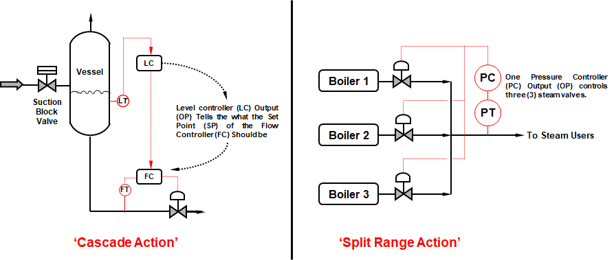
Some of the pro's and con's of Cascaded Action are,
- To improve speed and response to fluctuations by eliminating the effects of disturbances.
- Cascading provides better feed forward control. For example, in the above figure, any disturbances in the liquid level due to sudden inflow of liquid, the Level controller (LC) does not get perturbed but continues to record liquid level and adds feed forward compensation to the flow controller (FC).
- However the disadvantage is the cost increase with additional sensors, transmitters and controllers.
 Click Here to Join the Over 3200 Students Taking our Highly Rated Courses on Quality Assurance/Quality Control, Project Management, Engineering, Food Safety, Lean Six Sigma, Industrial Safety (HSE), Lean Manufacturing, Six Sigma, ISO 9001, ISO 14001, ISO 22000, ISO 45001, FSSC 22000, Product Development etc. on UDEMY.
An Example Application of Split Range Controller & HYSYS Setup
LNG Regasification terminals serve the purpose of vaporizing liquefied natural gas (LNG) received from LNG Tankers and feeding the vapours to consumers through pipelines.
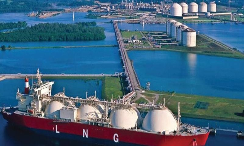
LNG is received into a cryogenic storage tank that operates below -160 deg.C and is sent to a heater with a fancy name called submerged combustion vaporizer (SCV). SCV’s consist of a series of tubes through which LNG flows and is heated by fuel gas that heats up the tubes and vaporizes the LNG.
The other alternative type of heater is called open rack vaporizers (ORV) that has a bunch of cooling coils exposed to sea water flow to vaporize LNG. Pumps are used to draw liquid from LNG cryogenic tanks and fed to SCV’s / ORV’s. In order to ensure the vaporized natural gas exits these heaters at the right pressure, temperature and flow rates, the LNG pumps which are fitted with a VFD must also operate at right speed.
 Click Here to Join the Over 3200 Students Taking our Highly Rated Courses on Quality Assurance/Quality Control, Project Management, Engineering, Food Safety, Lean Six Sigma, Industrial Safety (HSE), Lean Manufacturing, Six Sigma, ISO 9001, ISO 14001, ISO 22000, ISO 45001, FSSC 22000, Product Development etc. on UDEMY.
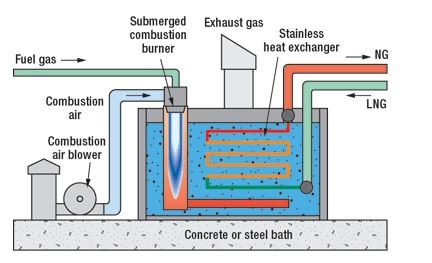
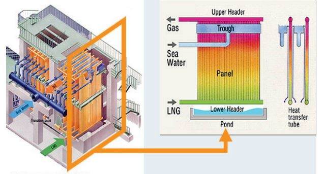
The following article demonstrates the use of High Pressure (HP) VFD Operated LNG pumps that controls the LNG pressure and a flow control valve a.k.a vaporizer control valve that controls pump flow. This ensures that the right amount of flow passes through the SCV/ORV’s. The problem in question when LNG vaporizer and transportation system operate is
- Any change in the pump speed causes a change in discharge pressure in the LNG pump.
- Any change in the vaporizer control valve causes a change in LNG flow fed to the vaporizers.
Hence a cascaded split range controller (SRC) can be used to to alter the pump speed and vaporizer valve opening to ensure the right amount of LNG at the required pressure, flow and temperature flows through the system.
 Click Here to Join the Over 3200 Students Taking our Highly Rated Courses on Quality Assurance/Quality Control, Project Management, Engineering, Food Safety, Lean Six Sigma, Industrial Safety (HSE), Lean Manufacturing, Six Sigma, ISO 9001, ISO 14001, ISO 22000, ISO 45001, FSSC 22000, Product Development etc. on UDEMY.
HYSYS Modelling of Cascaded Split Range Controller
An LNG stream of 7500 kmol/h at 12 bara and -160 deg.C is pumped to a vaporizer at 95 bara. The HP pump rated at 3000 rpm, runs at 2950 rpm while the design flow of the vaporizer is 7534 kmol/h. The vaporizer outlet temperature required is 2.5 deg.C. A split range controller (SRC) is added that alters the pump speed and vaporizer control valve to maintain the LNG Send Out at 7500 kmol/h.
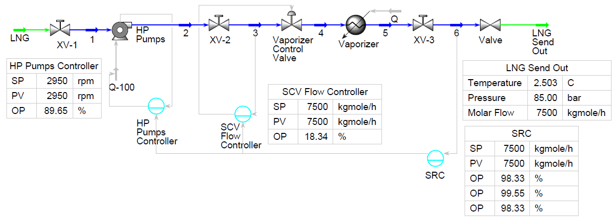
The HP pump operates with a speed controller and the vaporizer control valve operates with a flow controller - both of which are 'reverse acting'. This means that when the process variable (PV) (speed) goes up, the power fed to the pump (OP) drops. Similarly, when the LNG flow increases through the vaporizer control valve, the valve closes accordingly to maintain the required flow. Adding an SRC in HYSYS, the parameters can be declared as follows,
 Click Here to Join the Over 3200 Students Taking our Highly Rated Courses on Quality Assurance/Quality Control, Project Management, Engineering, Food Safety, Lean Six Sigma, Industrial Safety (HSE), Lean Manufacturing, Six Sigma, ISO 9001, ISO 14001, ISO 22000, ISO 45001, FSSC 22000, Product Development etc. on UDEMY.
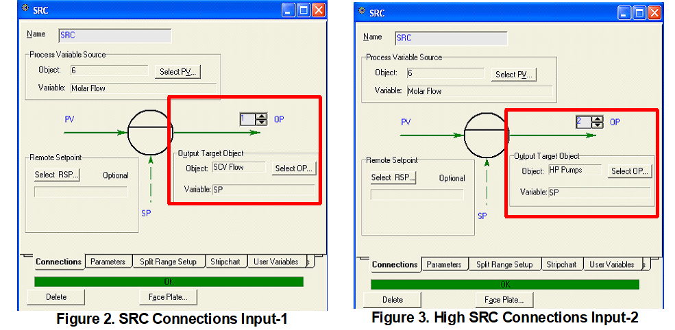
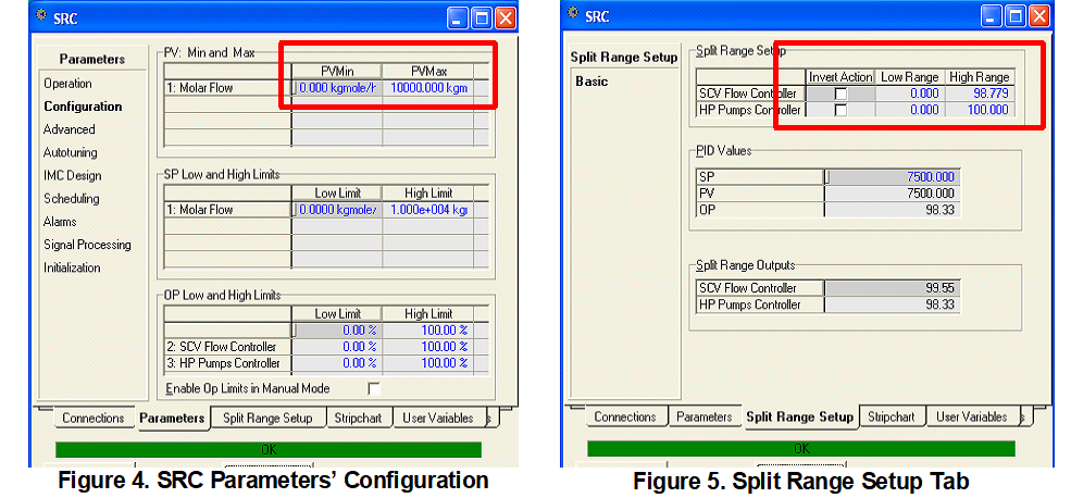
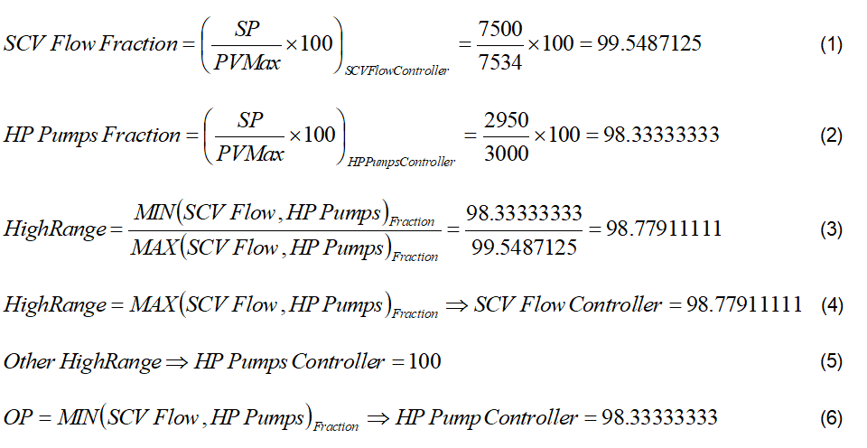
Upon entering the SCV Flow Controller as the first input and HP Pumps Controller as the second input, under the configuration window as shown in Fig. 4, enter the PVMin value as 0 kmol/h and 10,000 kmol/h in the PVMax Window. In the Split Range Setup Tab, the low range and high range values as shown in Fig. 5 are calculated as shown in Eq. 1 to Eq. 6.
 Click Here to Join the Over 3200 Students Taking our Highly Rated Courses on Quality Assurance/Quality Control, Project Management, Engineering, Food Safety, Lean Six Sigma, Industrial Safety (HSE), Lean Manufacturing, Six Sigma, ISO 9001, ISO 14001, ISO 22000, ISO 45001, FSSC 22000, Product Development etc. on UDEMY.
The value computed in Eq. 3 is assigned as the highest fraction to SCV Flow controller as shown in Fig 5 while the HP Pumps controller high parameter is always assigned 100.
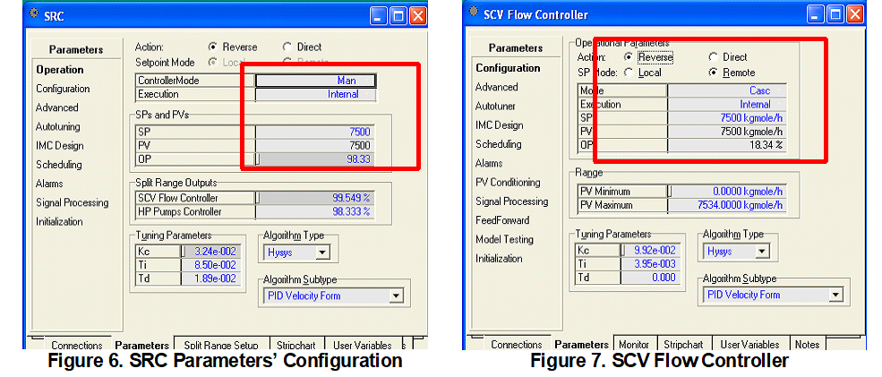
Note that the Low Range Values for both controllers in the Split Range Setup Tab (Fig. 5) is entered as ‘zero’. Followed by this, the lower fraction of 98.33 is assigned to OP cell in the parameters page (Fig. 6). It is recommended to use a PI controller with IMC tuning methods as a start and add derivative action (if necessary) depending on system response to avoid an oscillatory behavior of the controller.Lastly, the individual SCV flow controller (Fig. 7) and HP Pumps controllers (Fig. 8) are to be transferred to ‘Casc’ mode and the simulation has to be run for a while.
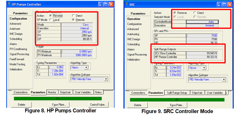
With the SRC controller being changed to ‘Auto’ mode (Fig. 9), the HYSYS model stabilizes to arrive at a final operating point similar to the individual controllers’ original set points (SP’s) of 2950 rpm and 7500 kmol/h. As a check, note that the Split Range Outputs match with the values of Eq. 1 and Eq. 2.
 Click Here to Join the Over 3200 Students Taking our Highly Rated Courses on Quality Assurance/Quality Control, Project Management, Engineering, Food Safety, Lean Six Sigma, Industrial Safety (HSE), Lean Manufacturing, Six Sigma, ISO 9001, ISO 14001, ISO 22000, ISO 45001, FSSC 22000, Product Development etc. on UDEMY.
About the Author
Vijay Sarathy holds a Master’s Degree in Chemical Engineering from Birla Institute of Technology & Science (BITS), Pilani, India and is a Chartered Engineer from the Institution of Chemical Engineers, UK. His expertise over 16 years of professional experience covers Front End Engineering, Process Dynamic Simulation and Subsea/Onshore pipeline flow assurance in the Oil and Gas industry. Vijay has worked as an Upstream Process Engineer with major conglomerates of General Electric, ENI Saipem and Shell.
