प्रोपेन-प्रोपलीन स्प्लिटर्स के लिए वाष्प संपीड़न
Propane-Propylene (C3) splitters are used in Petrochemical industries to distill propylene from propane prior to export. C3 Splitter columns are traditionally operated with low pressure steam (LPS) passed to the column’s reboiler to heat up the C3 mixture thereby causing the splitting operation. However the use of Low Pressure steam is energy-demanding. A C3 splitter is equipped with a cooler and flash tank at the column top that condenses the column top vapours but in doing so, loses precious heat of condensation. In recent years, the concept of using a heat pump, such as a compressor has become a standard practice that eliminates the necessity of using low pressure steam.
 Click Here to Join the Over 3200 Students Taking our Highly Rated Courses on Quality Assurance/Quality Control, Project Management, Engineering, Food Safety, Lean Six Sigma, Industrial Safety (HSE), Lean Manufacturing, Six Sigma, ISO 9001, ISO 14001, ISO 22000, ISO 45001, FSSC 22000, Product Development etc. on UDEMY.
C3 Splitter with Vapour Compression
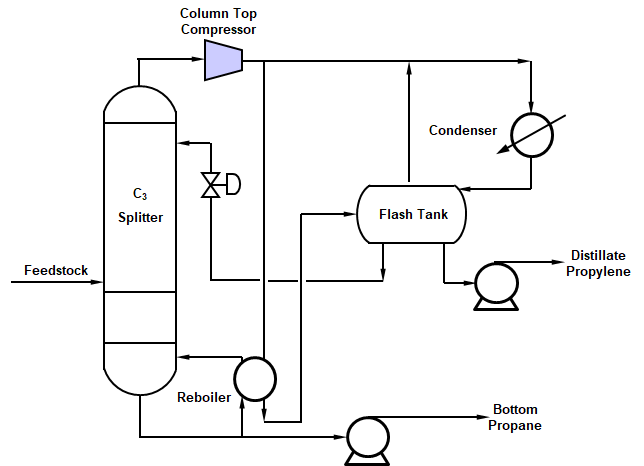
Vapour compression methods for C3 stripping operations are ideal for compounds that have low relative volatilities. Below is a schematic of a C3 splitter with vapour compression of product (propylene). Low pressure steam that was used to vaporize the bottoms propylene product is replaced by installing a column top compressor and routing a portion of the discharge to vaporize the bottoms propane via the reboiler.

As per Ref [2], for a C3 splitter to operate effectively, the temperature difference between the column top and bottom should not be more than 250F (13.90C). Additionally, the bottom heat of vaporization should be close to overhead vapour’s heat of condensation with a pressure drop less than 15 psi (1 bar) across the column internals. The heats of vaporization for propylene and propane are nearly close at 157.6 Btu/lb and 151.7 Btu/lb respectively. The excess energy required to be supplied by the compressor is around 11%-12% of reboiler duty [Ref 2] which represents a high energy savings. Low pressure strippers also offer the advantage of fewer trays, shorter column height and lower column wall thickness that represents a capital savings with higher relative volatilities to effectuate product separation.
 Click Here to Join the Over 3200 Students Taking our Highly Rated Courses on Quality Assurance/Quality Control, Project Management, Engineering, Food Safety, Lean Six Sigma, Industrial Safety (HSE), Lean Manufacturing, Six Sigma, ISO 9001, ISO 14001, ISO 22000, ISO 45001, FSSC 22000, Product Development etc. on UDEMY.
Low pressure C3 Stripper columns operate between 90 psig (6.2 barg) to 110 psig (7.6 barg) depending on the Technology Licensor. For the heat pump, the choice of compressor used can be centrifugal type with a typical pressure ratio of 1.8 [Ref 2] and effectively regulates the column top pressures when the throughput varies. The operation of the centrifugal compressor can be fixed type or variable speed type with the latter representing greater control but with higher installation costs.
C3 Column Top Pressure Control Methods
Suction Throttling Method
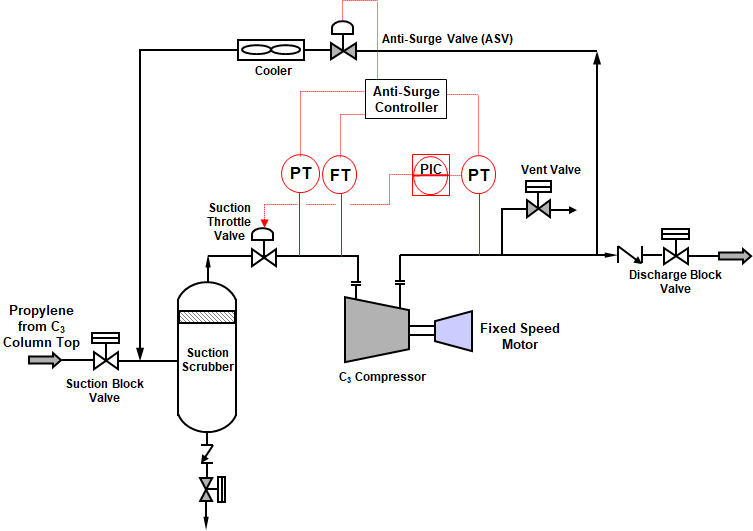
The Suction throttling method involves using a control valve (e.g. butterfly valve) placed at suction side of the centrifugal compressor. But these are suitable only for fixed speed drives like Asynchronous Induction Motors where the driver speed cannot be manipulated. Below is a process schematic of a C3 column top compressor that works on the principle of suction throttling. A cooler on the anti-surge line cuts down the inline pressure loss in the compressor discharge and also reduces the compressor discharge side equipment and piping volumes, contributing to the fast response of the anti-surge system. The PIC on the compressor discharge receives discharge pressures from discharge side pressure transmitter (PT) to alter the suction throttle valve opening.
 Click Here to Join the Over 3200 Students Taking our Highly Rated Courses on Quality Assurance/Quality Control, Project Management, Engineering, Food Safety, Lean Six Sigma, Industrial Safety (HSE), Lean Manufacturing, Six Sigma, ISO 9001, ISO 14001, ISO 22000, ISO 45001, FSSC 22000, Product Development etc. on UDEMY.

For C3 column operation, when the operating pressure at the column top increases, the suction throttle valve is altered based on the compressor discharge pressure. The operational advantage would be as follows,
- For the case where the column top pressure increases, it results in more propylene flow into the compressor. This causes the motor to draw in more amperage to sustain the required higher torque but can trip the electric motor and subsequently the compressor. Therefore, the suction throttle valve in such an event closes accordingly to ensure the discharge pressure required is maintained without tripping the compressor.
- In the event, the C3 column pressure falls, and for a fixed speed of the motor and reduced throughput from the column top, the compressor discharge pressure would rise causing the column top flash tank pressure and the bottom reboiler pressure to exceed design limits. Therefore as an abatement measure, the suction throttle valve would open further to maintain the required compressor discharge pressure.
- For both cases of C3 column top pressure increasing/decreasing, the anti surge valve (ASV) also acts in tandem with the suction throttle valve via the Anti-surge controller. This ensures that the compressor operating point does not cross the surge control line (SCL).
- From an energy savings perspective, the pinching operation of the suction throttle valve would make the compressor operate closer to the surge line where the power absorbed is lower.
 Click Here to Join the Over 3200 Students Taking our Highly Rated Courses on Quality Assurance/Quality Control, Project Management, Engineering, Food Safety, Lean Six Sigma, Industrial Safety (HSE), Lean Manufacturing, Six Sigma, ISO 9001, ISO 14001, ISO 22000, ISO 45001, FSSC 22000, Product Development etc. on UDEMY.
Variable Speed Motor (VSM) Method
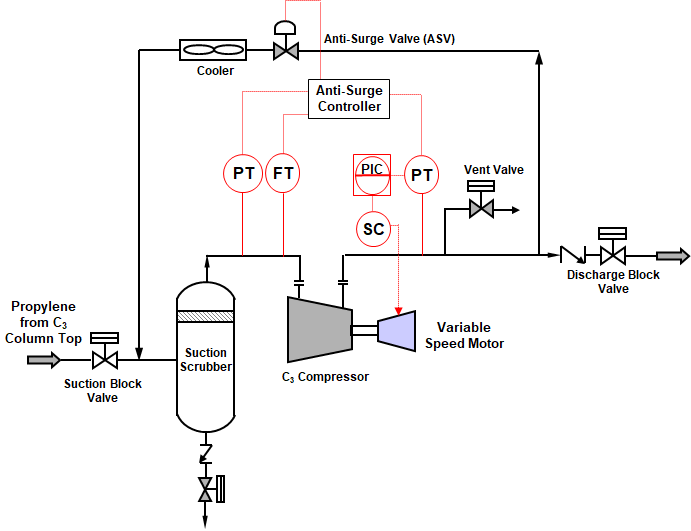
As an alternative, variable speed motor eliminates the need for a suction throttle valve and can cater to the tower top propylene vapours during column fluctuations by altering the motor speed based on the discharge pressure of the compressor. The discharge side pressure controller PIC cascades its output (OP) to assign a set point to the speed controller (SC) and controls the motor speed. In doing so, both output flow and pressure are regulated.
In real situations, C3 splitter columns can also experience fluctuations in operating pressures due to any changes in the upstream side of the C3 splitter. This would also mean the C3 splitter column would take a while to again attain equilibrium across trays and the vapour compressor at the tower top would also need to synchronize itself with the column operating pressures.

 Click Here to Join the Over 3200 Students Taking our Highly Rated Courses on Quality Assurance/Quality Control, Project Management, Engineering, Food Safety, Lean Six Sigma, Industrial Safety (HSE), Lean Manufacturing, Six Sigma, ISO 9001, ISO 14001, ISO 22000, ISO 45001, FSSC 22000, Product Development etc. on UDEMY.
Suction throttling Vs. Variable Speed Methods
- Suction throttling methods though can be used but suffer from an operability range of the throttle valve. This often requires the anti surge valve (ASV) to open frequently to avoid the compressor operating point from crossing the surge control line (SCL). A disadvantage of the suction throttling method is, during a reduction in the column top pressure, when the compressor operates closer to the surge line though saving power, the risk of the operating point crossing the surge line is high. Any further fluctuation in the column top pressure is detrimental in creating a Level 1 emergency equipment shutdown (ESD-1) scenario and subsequent upsetting of the column pressure profile. Additionally due to excessive pressure drop across small throttle valve openings, the risk of Joule-Thompson cooling can produce condensate particles which can erode the compressor’s impellers.
- Variable speed compressors also cater well during turndown conditions, as much as 30%. However this must be considered during the process design basis stage when setting the design and operating limits of the C3 splitter column. For such low turndown conditions, the compressor vendor must also be consulted prior to equipment selection to understand how much vapour recycling can occur via the anti-surge valve during such low turndown conditions.
- In vapour compression methods, when the use of steam is eliminated to vaporize the bottoms product, the tower top vapours from the compressor are used to effectuate vaporization of the bottoms product in the reboiler. In the event of the column operating pressure exceeding the stipulated values, variable speed drives reduce the compressor speed and hence discharge pressure, thereby supplying a reduced throughput to the reboiler. This consequently reduces the reboiler temperatures, reboiler vaporization rates, avoids product degradation and aids in bringing the operating pressure of the C3 splitter columns within the allowable limits.
References
 Click Here to Join the Over 3200 Students Taking our Highly Rated Courses on Quality Assurance/Quality Control, Project Management, Engineering, Food Safety, Lean Six Sigma, Industrial Safety (HSE), Lean Manufacturing, Six Sigma, ISO 9001, ISO 14001, ISO 22000, ISO 45001, FSSC 22000, Product Development etc. on UDEMY.
About the Author
Vijay Sarathy holds a Master’s Degree in Chemical Engineering from Birla Institute of Technology & Science (BITS), Pilani, India and is a Chartered Engineer from the Institution of Chemical Engineers, UK. His expertise over 16 years of professional experience covers Front End Engineering, Process Dynamic Simulation and Subsea/Onshore pipeline flow assurance in the Oil and Gas industry. Vijay has worked as an Upstream Process Engineer with major conglomerates of General Electric, ENI Saipem and Shell.
